
Cleanroom Ventilation Improvement with CFD Simulation
Cleanroom Ventilation Improvement with CFD Simulation
ARTICLES
Wiratama
12/4/20252 min read
Cleanrooms are controlled environments engineered to maintain extremely low concentrations of airborne particles. Their quality is defined by the maximum allowable number of particles per cubic meter at specified sizes. For reference, typical urban air may contain tens of millions of particles per cubic meter ≥ 0.5 µm, whereas an ISO 1 cleanroom permits only a few particles at smaller diameters. Because many pharmaceutical, semiconductor, optical, and biomedical processes are highly sensitive to contamination, cleanroom airflow control must be approached carefully during early design.
Ventilation configuration, duct layout, and recirculation characteristics significantly influence particle transport, thermal behavior, pressure balance, and long-term operating cost. Design choices made during planning ultimately affect construction scope, energy use, and compliance with performance standards. Simulation-based analysis provides a practical method for studying these outcomes prior to installation.
Using Flow Simulation to Guide Cleanroom Design
To demonstrate the role of CFD in cleanroom optimization, consider a contaminant leakage scenario evaluated under three different ventilation configurations. In all cases, fresh supply air enters as a single-pass flow, allowing comparison on equal terms.
Configuration Overview
Central ceiling inlets with floor-level exhaust
Distributed ceiling inlets with floor-level exhaust
Raised perforated floor with subfloor exhaust and distributed ceiling inlets
The evaluation focuses on airflow uniformity, recirculation zones, and the tendency of contaminants to linger within occupied areas.
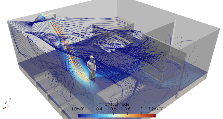
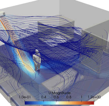
Velocity Field Observations
With identical boundary conditions, velocity contours reveal distinct differences among the layouts:
Configuration 1 shows large recirculation regions, especially near walls and corners. Recirculation increases the risk of contaminant retention and undesirable mixing.
Configuration 2 distributes supply air more evenly overhead, reducing recirculation in critical work zones.
Configuration 3 demonstrates the least recirculation. Flow primarily sweeps downward and exits through the perforated floor, concentrating recirculation only at non-critical peripheral areas.
For cleanrooms requiring downward laminar flow, this type of pattern is preferred. ISO 1–4 classifications typically mandate unidirectional vertical airflow, reinforcing the need to minimize lateral mixing.
Another key variable is total supply volume. Certain instruments require strict pressure or temperature conditions, so air change rates and duct capacities must be sized carefully. Flow simulation helps confirm pressure uniformity, evaluate pressure drop across tiles and filters, and tune recirculation characteristics prior to commissioning.
Contaminant Propagation Comparison
The same leakage source is modeled in all three scenarios, and a cross-sectional scalar field is used to observe dispersion paths:
Configuration 1 allows contaminant movement up to ceiling level due to recirculation loops.
Configuration 2 directs the contaminant toward the nearest exhaust location, though performance may vary if the release point shifts.
Configuration 3 consistently draws the contaminant downward through the perforated flooring, regardless of source location. Extraction through the subfloor plenum prevents contact with work surfaces and substantially reduces risk exposure.
From both velocity and scalar field analysis, Configuration 3 provides the most robust mitigation behavior.
Conclusion
Cleanroom layouts, duct placement, inlet design, and pressure management have significant influence on cleanliness, safety, and energy demand. Improving airflow uniformity, minimizing recirculation, and capturing contaminants through predictable exhaust pathways are central goals of cleanroom ventilation.
CFD-based analysis supports these decisions by revealing flow direction, stagnation zones, pressure gradients, and contaminant transport before construction begins. Used properly, it helps designers refine geometry, optimize supply-extraction balance, tune cleanroom classifications, and reduce unnecessary energy use.
Advance Critical Cleanroom Decisions with tensorHVAC-Pro
Whether you are shaping laminar flow systems, sizing air change rates, evaluating tile porosity, or tracing contaminant pathways, tensorHVAC-Pro provides CFD-based capabilities engineered for high-precision cleanroom design. It enables ventilation optimization, risk mitigation, and performance validation—helping you achieve cleaner, safer, and more efficient controlled environments.
tensorHVAC-Pro is a dedicated HVAC flow and thermal simulation software, Intuitive and easy to use, designed for HVAC engineers - not CFD expert. Learn more..
Read more articles..