
Ducting design with flow and thermal simulation
Using Computational Fluid Dynamics (CFD) software to simulate detailed flow and thermal behaviour of HVAC ducting system and its interaction with the room
CASE-STUDIES
Wiratama
10/21/20253 min read
Ducting Flow and Thermal Design with CFD Simulation
In HVAC system design, ducting flow and thermal performance play a critical role in ensuring energy efficiency, comfort, and indoor air quality. Poorly designed ducts can lead to uneven temperature distribution, noise, pressure losses, and wasted energy. To overcome these challenges, engineers are increasingly turning to Computational Fluid Dynamics (CFD) simulation, a digital method that predicts airflow and heat transfer behavior before installation. With CFD, ducting systems can be designed and optimized based on physics, not assumptions — reducing rework, cost, and performance risks.
Understanding Ducting Flow and Thermal Behavior
Ducting systems serve as the arteries of HVAC installations, delivering conditioned air from air-handling units to occupied spaces and returning it back for recirculation. Within this network, airflow uniformity, pressure drop, and heat loss or gain are the primary design concerns.
Flow design focuses on achieving balanced air velocity and minimizing turbulence or recirculation.
Thermal design ensures that temperature remains within acceptable ranges, accounting for duct insulation and ambient conditions.
CFD simulation enables engineers to analyze these factors together — providing a complete picture of how air moves, mixes, and exchanges heat throughout the duct system.
Why Use CFD Simulation for Ducting Design
Traditional duct design relies on manual calculations or empirical formulas that assume ideal flow. In reality, ducts feature bends, branches, and fittings that disturb airflow, causing losses and inefficiencies. CFD allows engineers to visualize these effects directly and make data-driven improvements.
Key benefits include:
Accurate airflow prediction — Evaluate velocity distribution, turbulence, and pressure drops across ducts.
Thermal performance analysis — Identify temperature variations due to conduction or inadequate insulation.
Noise and vibration assessment — Detect high-velocity regions that may generate noise or resonance.
Energy optimization — Reduce fan power by minimizing unnecessary pressure losses.
Design validation — Ensure even air distribution across diffusers and rooms before construction.
By simulating real operating conditions, CFD replaces guesswork with insight — ensuring the final duct layout performs as intended.
CFD Process for Ducting Flow and Thermal Analysis
Geometry Modeling
Create a 3D representation of the duct network, including main trunks, branches, elbows, and diffusers. Complex building layouts can be simplified for computational efficiency.Meshing
Divide the geometry into small computational cells. A finer mesh is applied near bends, junctions, and diffusers to capture detailed flow characteristics.Boundary Conditions
Define airflow rate, inlet velocity, temperature, and outlet pressure. For thermal analysis, specify insulation thickness or external heat exposure.Solver Setup
CFD software solves governing equations for mass, momentum, and energy conservation using appropriate turbulence models like k–ε or k–ω SST.Post-Processing and Analysis
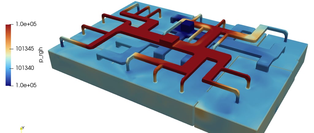
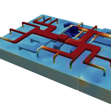
Visualize results through velocity contours, streamlines, temperature maps, and pressure loss charts. Identify flow separation zones, dead air regions, or high-friction areas.
This digital workflow allows iterative testing of different duct configurations, optimizing the system’s performance before a single duct is installed.
Using tensorHVAC-Pro for Ducting CFD Simulation
Unlike general-purpose CFD tools that require advanced setup, tensorHVAC-Pro is tailored for HVAC engineers — offering an intuitive interface that automates complex steps while maintaining professional accuracy.
With tensorHVAC-Pro, engineers can:
Simulate duct airflow and thermal distribution quickly and accurately.
Evaluate pressure loss, velocity uniformity, and temperature gradients in 3D.
Visualize comfort parameters such as air temperature and flow balance in supply zones.
Optimize diffuser positions and duct geometry for improved energy efficiency.
Its dedicated HVAC-focused workflow eliminates the need for CFD expertise, making advanced flow and thermal analysis accessible to every engineer involved in duct design.
Real-World Application Example
Consider a commercial building with a long supply duct network feeding multiple zones. Using CFD simulation in tensorHVAC-Pro, the engineer identifies a high-pressure drop near a series of 90° elbows. By adjusting duct geometry and adding turning vanes, the revised design reduces fan power by 12% while maintaining uniform airflow. The result — better performance, lower energy use, and reduced system noise.
Conclusion
Ducting flow and thermal design defines the efficiency and comfort of any HVAC system. By integrating CFD simulation, engineers gain visibility into air behavior that is impossible to capture with manual methods. Software like tensorHVAC-Pro empowers HVAC professionals to analyze and optimize duct systems effortlessly — achieving balanced airflow, reduced energy consumption, and consistent thermal comfort.
With simulation-driven design, ductwork evolves from a guess-based layout to a scientifically optimized system — delivering reliable, efficient, and high-performance HVAC operation.
tensorHVAC-Pro is a dedicated flow and thermal HVAC simulation software, intuitive and easy to use, designed for HVAC engineers - not CFD expert
Read other case studies..