
FreeCAD HVAC CFD Simulation: Prepare the geometry from FreeCAD and Run Simulation in tensorHVAC-Pro
FreeCAD HVAC CFD Simulation: Prepare the geometry from FreeCAD and Run Simulation in tensorHVAC-Pro
ARTICLESFEATURES
Wiratama
11/13/20255 min read
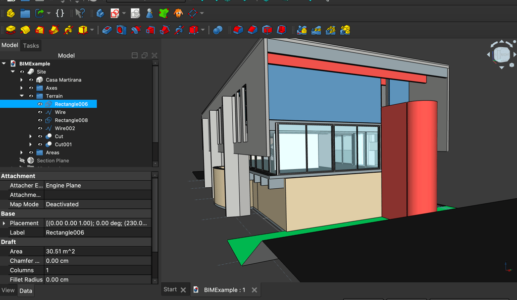
Preparing Geometry in FreeCAD
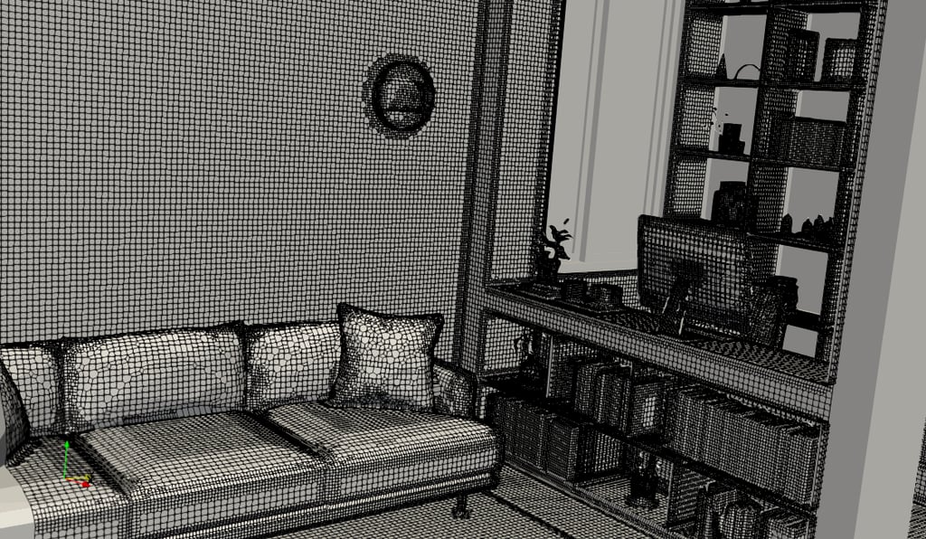
When simulating HVAC systems using FreeCAD, the first crucial step is to prepare the geometry accurately. The integrity of the simulation results largely depends on how well the geometry is defined, particularly for the inlets and outlets of the HVAC system. In FreeCAD, users can create, modify, and optimize the geometry with relative ease, which is highly beneficial for achieving desired simulation outcomes.
To begin with, it is essential to ensure that all surfaces intended for air entry and exit are properly defined. This involves creating distinct boundary surfaces for each component of the HVAC system, such as ducts, fans, and air diffusers. Using FreeCAD’s intuitive interface, users can generate primitives or import existing models, allowing a high degree of customization. It is advisable to leverage the parametric modeling capabilities of FreeCAD to adjust dimensions and orientations efficiently, ensuring that they meet the specific requirements of the planned HVAC design.
Moreover, one of the standout features of FreeCAD is its capability to eliminate the need for converting geometry to a negative domain, a process that can complicate simulations in traditional Computational Fluid Dynamics (CFD) software. By defining surfaces correctly and ensuring they are oriented properly, users can proceed directly to simulation without the additional complexity. This not only saves time but also reduces potential errors associated with geometry conversion.
Additionally, keeping the geometry clean and minimizing unnecessary complexity is vital. Each surface should be smooth and free from extraneous details that may hinder simulation processing. Focused attention on these aspects will lead to a robust and efficient setup for HVAC simulations, enabling users to achieve accurate and reliable results in analyses.
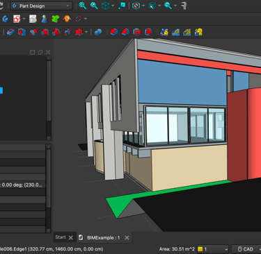
Exporting Geometry in STL Format
Exporting geometry from FreeCAD into the STL format is an essential step in preparing models for simulation in HVAC systems. The STL (Stereolithography) file format is widely accepted in various simulation software, making it crucial for accurate representation and analysis of geometrical designs. Follow these steps to effectively navigate the FreeCAD interface and ensure a successful export of your geometry.
First, ensure that your model is fully prepared and all necessary features have been incorporated. Subsequently, you will need to optimize the mesh to enhance the quality of your export. To do this, select the object you want to export within the FreeCAD model tree. Navigate to the “Part” workbench, and from the top menu, choose “Create shape from mesh.” This function helps convert your model into a form that can be more easily exported.
Once your shape is appropriately created, go to the File menu and select “Export.” In the dialog box that appears, choose the STL format from the available options. It’s vital to ensure that your geometry adheres to simulation standards during this process. Check the dialog settings for any parameters that may need adjustments, such as modifying the mesh resolution or specifying other export properties depending on your simulation requirements.
If you encounter difficulties during the export process, consider common troubleshooting tips. Errors can often arise from complex geometries or non-manifold edges. Utilize FreeCAD’s analysis tools to identify and rectify any issues in your design prior to initiating the export. By ensuring that your geometry is simplified and meets the necessary requirements, you can mitigate exporting problems, thereby enhancing your simulation workflow.
Importing STL Files into tCFD-PRE
To initiate the process of leveraging FreeCAD-generated STL files in TCFD-PRE, it is essential to follow a systematic approach. The first step involves exporting the 3D model from FreeCAD as an STL file. Ensure that the file is appropriately named and saved in a location that is easily accessible. Once the STL file is prepared, open TCFD-PRE and navigate to the import feature, typically located in the file menu. Select "Import" and locate the STL file you previously saved. Upon selection, TCFD-PRE will begin processing the geometry, converting it into a form suitable for simulation.
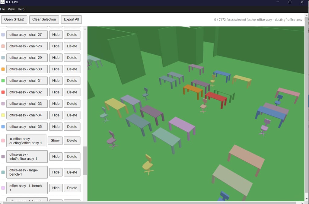
After importing the STL file, the next step is to define boundary conditions, which are critical parameters that influence simulation accuracy. Boundary conditions dictate how the fluid flows interact with the surfaces of the geometry. In HVAC simulations, defining these boundaries correctly ensures that the model responds realistically to various environmental variables. You can select specific surfaces within your imported geometry to designate as boundaries. This can often involve highlighting the desired surface and specifying the conditions such as inlet, outlet, or wall types.
For instance, in a ventilation system simulation, you might set the air supply ducts as inlets while exhaust points can be labeled as outlets. It is crucial to apply the right thermal and fluid parameters for each surface, as this will directly affect the heat transfer and airflow behavior in your model. Additionally, tCFD-PRE provides tools to visualize boundary conditions, which can assist in identifying and correcting any potential configuration issues. Throughout this process, refer to provided visuals and practical examples to enhance your understanding of each step.
Setting Up and Running Simulations in tensorHVAC-PRO
To effectively utilize TensorHVAC-PRO for simulating HVAC systems, the initial step involves configuring the simulation environment appropriately. Begin by initializing the software and creating a new project. This sets the foundation for modeling various components of the HVAC system. Once you have your project established, the next crucial phase is defining the physical properties of your model. This includes inputting parameters such as duct sizes, material types, and airflow characteristics, ensuring that the properties align with the actual specifications of the HVAC installation.
After setting up the physical attributes, proceed to configure simulation parameters. These may encompass factors like temperature settings, pressure conditions, and other operational specifics relevant to your system's functional requirements. It’s important to meticulously check these inputs to ensure an accurate representation of the HVAC dynamics. Furthermore, you might need to consider applying certain additional settings unique to your simulation goals, which could include performance benchmarks or energy efficiency targets.
Once the foundational elements are configured, the simulation can be commenced. During this run, it is advisable to closely monitor progress through the intuitive dashboard provided by TensorHVAC-PRO. This interface allows users to track various metrics in real-time, which aids in identifying any anomalies that may arise during the simulation. As results begin to materialize, analyzing the outputs becomes critical for validating the design’s effectiveness. Utilize the built-in tools within TensorHVAC-PRO to interpret these results effectively, paying attention to parameters such as air flow distribution and temperature gradients.
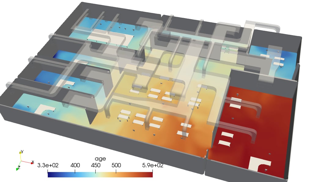
In cases where discrepancies or issues occur, having a troubleshooting strategy is vital. Common issues may include convergence errors or unrealistic output values. Review the input parameters meticulously, adjust physical properties if necessary, and ensure that all components of the system are correctly defined within the model. Following these best practices will not only validate your HVAC design but also enhance your overall simulation experience with TensorHVAC-PRO.
tensorHVAC-Pro is a dedicated HVAC flow and thermal simulation software, Intuitive and easy to use, designed for HVAC engineers - not CFD expert. Learn more..
Read more tensorHVAC-Pro Features