
How to Simulate HVAC System using OpenFOAM
How to Simulate HVAC System using OpenFOAM
ARTICLES
Wiratama
11/27/20253 min read
How to Simulate HVAC Systems with OpenFOAM: Complete Beginner-to-Advanced Guide
Simulating HVAC (Heating, Ventilation, and Air Conditioning) systems with OpenFOAM allows engineers to analyze airflow distribution, temperature gradients, contaminant transport, ventilation efficiency, and thermal comfort inside buildings or mechanical spaces. While commercial tools like ANSYS Fluent or Star-CCM+ are often used in industry, OpenFOAM provides a powerful open-source alternative that is fully customizable.
This article explains the full workflow of running HVAC simulations using OpenFOAM — from geometry preparation to post-processing.
1. Define Your HVAC Simulation Objective
Before opening OpenFOAM, clarify the purpose of the analysis:
Airflow distribution inside a room
Ventilation effectiveness (ACH, age of air, CO₂ dispersion)
Temperature distribution (thermal comfort)
Pressure drop in ducts
HVAC diffuser performance
Data center cooling efficiency
Contaminant / smoke transport
Typical HVAC simulations involve turbulent and incompressible airflow, often with thermal coupling.
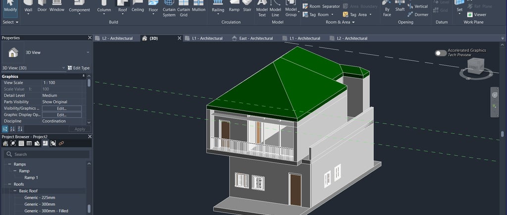
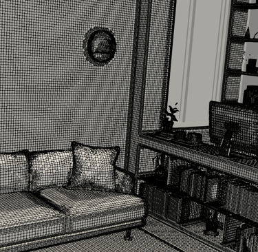
2. Prepare the Geometry
Create the geometry using CAD tools:
Simplify the model:
Remove bolts, screws, tiny fillets
Keep smooth, watertight surfaces
Represent diffusers and grilles accurately
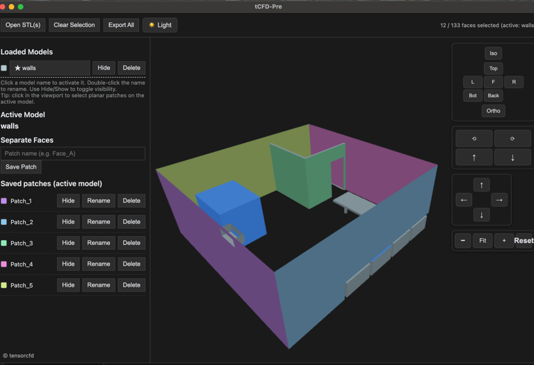
Export the geometry as STL.

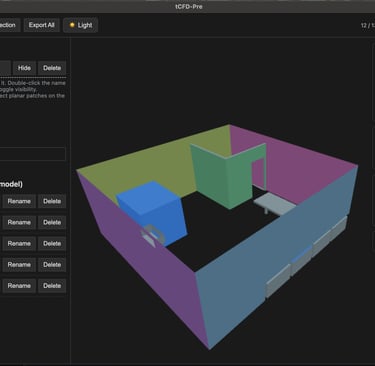
Your exported STLs are still in a single surface geometries, you can manage and separate them by using specialized STL editor for OpenFOAM, tCFD-Pre.
3. Mesh the Domain
You can mesh in:
snappyHexMesh (OpenFOAM built-in)
cfMesh
external meshing tools (Pointwise, Salome, etc.)
For HVAC:
Use hexa dominance for stability
Add refinement around diffusers, obstacles, and HVAC vents
Keep mesh non-orthogonality low
Use boundary layers for accurate wall modeling
Typical mesh sizes: 1–10 million cells

4. Select the Appropriate OpenFOAM Solver
HVAC simulations may involve airflow, heat transfer, and sometimes species transport. Choose based on physics:
A. For Airflow Only (Isothermal)
Use:
simpleFoam (steady-state, incompressible)
pimpleFoam (transient, incompressible)
B. For Airflow + Heat Transfer
Use:
buoyantSimpleFoam (steady-state or transient with large time-steps, buoyant)
buoyantPimpleFoam (transient with small time-steps buoyant)
These account for:
temperature
density-driven airflow
thermal stratification
C. For CO₂ / Contaminant Transport
Add scalar transport:
passiveScalarFoam
reactingFoam (if needed)
5. Set Up Boundary Conditions
Typical HVAC boundaries include:
Inlets (Diffusers or Supply Air)
Type: fixedValue for velocity
Velocity magnitude: based on diffuser specs
Temperature: supply air temperature
Turbulence: ( k ), ( \omega ), or turbulence intensity
Outlets (Return Air)
Type: pressure outlet
Zero gradient for velocity
Walls
No-slip wall
Thermal BC options:
fixed temperature
heat flux (q)
convective heat transfer
Furniture / Obstacles
Treated as solid walls
Optional heat generation
6. Choose Turbulence Model
For typical HVAC rooms or data centers:
k–ε (robust, widely used in ventilation CFD)
k–ω SST (better near-wall performance)
RNG k–ε (good for indoor airflow)
For high-quality indoor flow predictions:
Use RANS first, then LES if needed.
7. Run the Simulation
Use commands like:
blockMesh
snappyHexMesh -overwrite simpleFoam
or for thermal simulations:
buoyantSimpleFoam
For transient:
pimpleFoam
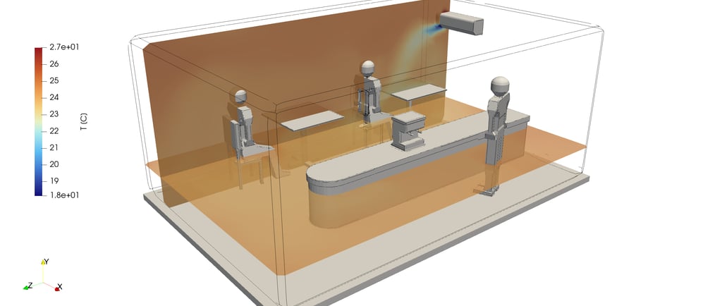
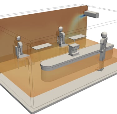
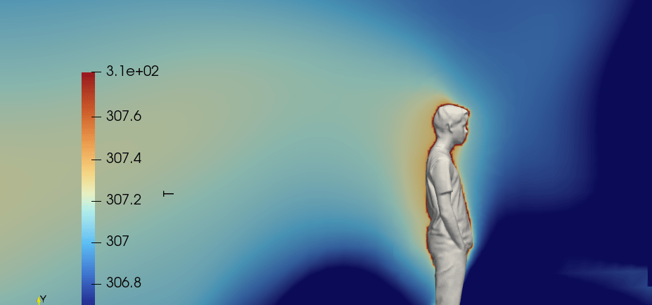
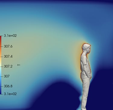
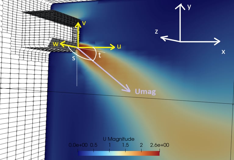
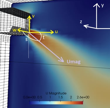
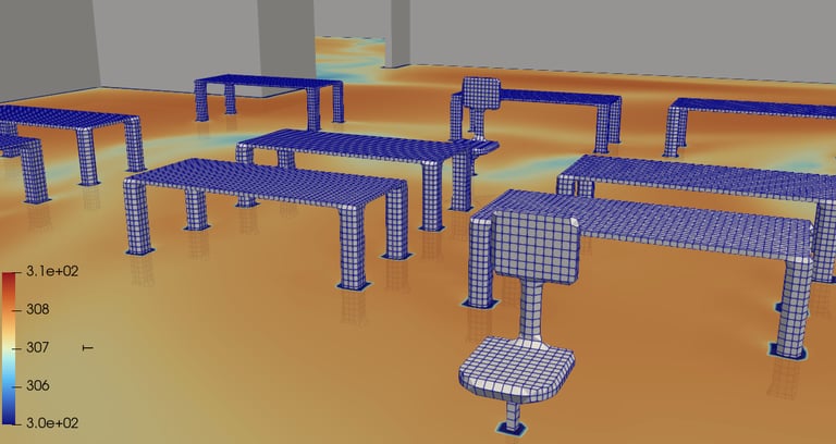
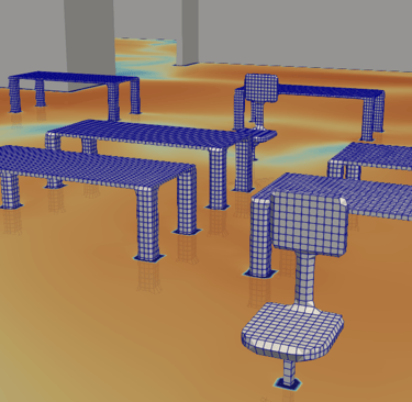
8. Post-Process in ParaView
Use ParaView to visualize:
Airflow streamlines
Temperature gradients
Velocity vectors
Pressure distribution
Contaminant dispersion
To export high-quality images from ParaView:
File → Save Screenshot → set resolution → Save
9. Validate the Simulation
Validation methods:
Compare with ASHRAE guidelines
Compare air velocity with diffuser datasheets
Compare temperature field with field measurements
Compare pressure drops with ducting standards
10. Best Practices for HVAC Simulations in OpenFOAM
Use refined mesh near supply vents
Set realistic boundary conditions from HVAC equipment specs
Start with steady-state, then shift to transient
Use LES for detailed contaminant tracking
Use CO₂ as tracer gas to evaluate ventilation effectiveness
Conclusion
Simulating HVAC systems with OpenFOAM is a powerful way to analyze indoor airflow and thermal comfort at a professional level. With the right solver, mesh strategy, and thermal boundary conditions, OpenFOAM can match the capabilities of commercial CFD tools—while offering full customization for advanced R&D.
If you want to simulate your HVAC project on OpenFOAM, but dont have time to learn the complex OpenFOAM user experience, please try tensorHVAC-Pro, a dedicated GUI of OpenFOAM for HVAC application.
tensorHVAC-Pro is a dedicated HVAC flow and thermal simulation software, Intuitive and Easy to use, designed for HVAC engineers - not CFD expert. Learn more..
Read more articles..